Sim68K - Hardware Window
Sim68K includes support for hardware simulation. To view the Hardware window, select 'Hardware' from the View menu.
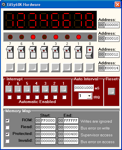
The hardware window displays an 8 digit 7-segment display, a bank of 8 light emitting diodes (LED), a bank of 8 toggle switches and a bank of 8 push button switches. Each of these hardware items may be mapped to any valid 68000 address by entering the desired address in the corresponding Address: field. If the address entered causes a conflict with another device the color of the address text will change to red.
The 7-segment display has each digit mapped to a successive word address beginning with the left-most digit. For example, in the above picture the digits are mapped to memory as follows:
DIGIT ADDRESS
1 E00000
2 E00002
3 E00004
4 E00006
5 E00008
6 E0000A
7 E0000C
8 E0000E
The toggle switches write a 1 to the corresponding bit in memory when the switch is on "Up" and write a 0 when the switch is off "Down".
The push button switches are normally high. They write a 0 to the corresponding bit in memory while the switch is pressed and write a 1 when the switch is released.
Interrupt
The Interrupt pushbuttons may be used to manually simulate an interrupt request. Pressing each button generates the corresponding interrupt request. For more on exception processing see Enable Exceptions under Simulator Options and exception processing.
An interrupt may be set to automatically create interrupts by selecting the desired interrupt in the "Auto Interval" drop down and then entering the interval in milliseconds. Checking the checkbox under the interrupt pushbutton enables auto interrupts for the corresponding interrupt.
The Reset pushbutton simulates a hardware reset.
Memory Map
A 68000 microprocessor contains 32 bit registers but externally it only supports a 24bit memory space from $00000000 through $00FFFFFF. Any attempt to access memory beyond $00FFFFFF results in the upper 8 bits of the address being ignored. Therefore, attempting to access memory location $nn002000, where nn is $01 through $FF, actually results in an access to $00002000. EASy68K emulates this behavior.
Six different types of memory access are supported by EASy68K, they are: RAM, Hardware, ROM, Read, Protected and Invalid. RAM is assumed unless otherwise specified. The memory types:
RAM - Read and Write
Hardware - Any of the simulated hardware devices from
the Hardware window above.
ROM - Read Only Memory, Writes are ignored.
Read - Read only, Writes result in a
Bus error.
Protected - Read and Write only if the Supervisor bit
in the Status Register is set, otherwise a Bus error
results.
Invalid - Any access results in a
Bus error.
The checkbox is used to enable/disable the corresponding memory type.
The simulator checks the memory map access in the following order: Hardware, Invalid, Protected, Read, ROM. Hardware accesses are always allowed.
The Memory assembler directive may be used to specify memory types in source code.
Trap task 32 may be used to interact with the simulated hardware from a program.
* All Addresses are entered in hexadecimal, the Auto Interrupt timer is a decimal value.