WATFORD ELECTRONICS
SOLDERLESS SIDEWAYS ROM BOARD
FOR THE BBC MICRO
The
Solderless Sideways ROM board for the BBC micro enables the user to increase the
sideways ROM capacity from the basic 4 sockets to the full 16 supported by
current operating systems.
FIITTING
INSTRUCTIONS
First
open the case of the BBC Micro by removing the four main case screws. Two of
these are at the back, and the other two under the keyboard. They may be marked
FIX. Remove the keyboard by undoing the two bolts at either end. Next remove
IC51; this is the OS ROM and is the fifth chip from the right under the
keyboard. It should be labelled “PB04” for OS 1.20. Plug this into
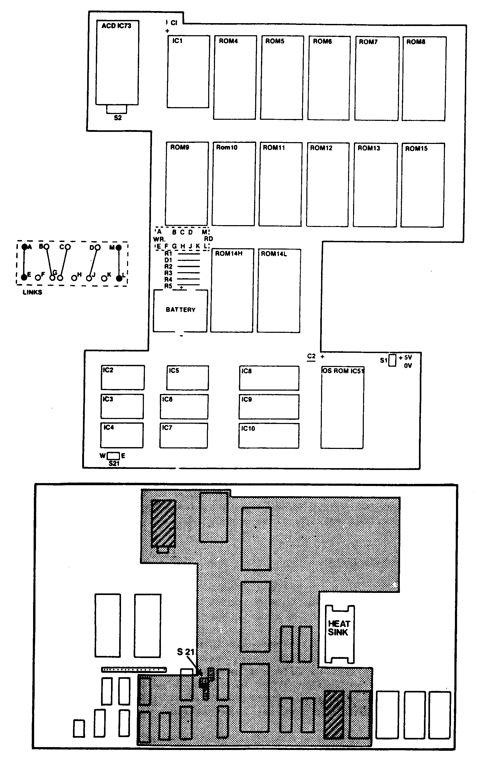
the ROM board bottom right hand socket on the ROM board labelled “OS
ROM”.
Now
remove IC73; this is the ADC chip which is at the rear of the computer just
below the joystick port. It should be labelled “D7002C”. Plug this
into the ROM top left board socket labelled “ADC”. Next locate link
S21, which is to the right of the keyboard cable. S21 consists of four posts
-
two sets of two running East/West (or
right/left). Remove and keep the link from the front most of these two links.
Then plug the flying wire labelled S21 from the 12 ROM board on to the newly
vacated posts of S21. The same orientation must be retained as on the 12 ROM
board ie. the wire from "S21 e” goes to the east (or right hand) part of
S21.
Finally
plug the whole board in. The OS ROM should be over its former socket as should
the ADC. Part of the board will go under the keyboard ribbon so make sure this
does not get in the way. Press the board firmly in place so it is stable. Having
done this, switch on the computer. If a continuous buzz is heard, make sure the
board is pressed firmly in place. If “Language?” appears on the
screen, you have probably plugged the flying wire the wrong way round on
S21.
OPERATION
The
ROM you want enter the machine is switched on (normally BASIC) should go in the
highest priority socket, which is socket 15. The BASIC ROM is labelled
“PB01” or “PB05”. If you have a disk system, the DFS ROM
should go in a low priority socket. Sockets 14L and 14H are different from the
other remaining sockets; they can take a variety of different chip types, with
links specifying what type is fitted. Two low capacity chips can be
‘linked’ together to behave as if they were one. The main use of
this is for sideways RAM, type 6264. The setting links are defined as follows
(the links are factory set for 2764/6462 chips):
14H 14L Links to be made 14H 14L Links to be
made
27128-2764 J to D, G to B 2764—2764
J to D, G to C, G to B, E to A
6264-2764 J to D, G to C, G to B, E to
A 6264-6264 J to D, G to C, G to B, E to
A
6116-6116 K to D, J to C, F to
B, E to A 6116-2716 K to D, J to C, F to B, E to
A
2716-2716 K to D, J to C, F to
B, E to A 2732-2732 H to C, F to B
Whenever
a write is made to a sideways ROM (in the region &8000 to &BFFF), it is
automatically directed to socket 14 which can take RAM. This means you can
"*LOAD" ROMs which you do not have room for, or directly assemble machine code
into this RAM. However it is sometimes desirable to disable this. Link E
to A is a push-on terminal which, when removed, protects the RAM from
write operations; ie it controls write protect. This can have a switch
coupled up to it instead for ease of use.
Link
L to M is a push-on terminal which, when removed,
protects the RAM in socket 14 from being read.
This is useful if an error occurs when developing a ROM in the sideways RAM. The
RAM can still be written to, so it can be altered safely. Provision is allowed
for the installation (via soldering) for a PCB mounting type Ni-Cad battery to
be fitted to maintain the contents of static RAM in sockets 14L
AND
14H, even when the BBC itself is turned off.
Watford
Electronics
Distributors of Electronic Components Micro
Computers & Peripherals
250 High Street,
Watford, WD1 2AN, England. Tel: Watford (0923)37774/40588. Telex: 8956095
WATFRD.
Watford 12
Socket
Solderless ROM
Board
A
number of users have encountered problems when fitting this board to their
computer's. To help you, we have distilled the problems and cures into a few
paragraph..
The
main problem encountered is that of components on the main board snagging with
the ROM board. The S21 and power leads may all need to be bent (very carefully)
to allow the board to rest comfortably in its two sockets. Towards the rear
right of 1C2 is a crystal. On some BBCs this crystal is very prominent from the
surface of the board and may require some insulation tape placing over it to
prevent potential shorts across the casing when the ROM board is
installed.
When
you are finally ready to push the ROM board home into the OS and ADC sockets,
ensure that ALL the pins are lined up BEFORE you start applying pressure. When
you do apply pressure, do so equally on the two sockets and push vertically
down. DO NOT apply any sideways pressure as this may result in you snapping some
or all of the pins due to excess force.
In
use, the two RAM sockets (14L and 14H - logical socket 14/&E) are only
active when accesses come from on the ROM board. This drastically cute down on
the power consumption of the board, but has the implication that you cannot, for
example, *LOAD filename 8000 with the DFS ROM located in one of the four
original sockets. The DFS ROM (and any other ROM that is going to perform writes
to the sideways RAM) needs to be located on the ROM board itself for these
writes to actually perform anything.
On
some BBCs we have encountered small surges that corrupt the sideways RAM on
power down and switch on. If you are using battery backed RAM, then it is
advisable to remove the Write protect link from the board before power down to
prevent any writes to the sideways RAM. Should corruption occur, you can remove
the Read protect link to allow the machine to power up.
Should
you be experiencing a problem with any of our products, and the above not
provide the solution, please write in with as many details as possible. Writing
in allows us to contact external authors, whereas telephone calls do not permit
this.
Technical
Support.


