|
|
|
MF501B
|
MF503B
|
MF504B
Low
density
|
MF504B
High
Density
|
|
|
MFM
recording
|
|
|
|
|||
|
Unformatted
capacity:-
|
Track
|
6.25KB
|
6.25KB
|
6.25KB
|
10.416KB
|
|
|
Disk
|
500KB
|
1000KB
|
1000KB
|
1666KB
|
||
|
Formatted
capacity:-
|
|
|
|
|
|
|
|
Sector
|
0.256KB
|
0.256KB
|
0.256KB
|
0.512KB
|
||
|
16
(15) sectors/
Track
|
Track
|
4.096KB
|
4.096KB
|
4.096KB
|
7.680KB
|
|
|
Disk
|
327.7KB
|
655.36KB
|
655.36KB
|
1228.8KB
|
||
|
Transfer
rate
|
|
250kb/S
|
250Kb/s
|
250/300Kb/s
|
500Kb/s
|
|
|
Track
density per inch
|
48
tpi
|
96
tpi
|
96
tpi
|
96
tpi
|
||
|
Total
tracks
|
|
80
|
160
|
160
|
160
|
|
|
Access
time
|
|
|
|
|
|
|
|
Track
to track
|
6
mS
|
3
mS
|
3
mS
|
3
mS
|
||
|
Average
|
103
mS
|
94
mS
|
94
mS
|
94
mS
|
||
|
Settling
time
|
15
mS
|
15
mS
|
15
mS
|
15
mS
|
||
|
Motor
speed
|
300rpm
|
300rpm
|
300/360rpm
|
300rpm
|
||
|
Motor
start time
|
250
mS
|
400
mS
|
400
mS
|
500
mS
|
||
|
Ready
time
|
700
mS
|
700
mS
|
700
mS
|
700
mS
|
||
|
Environmental
conditions
|
Operating
|
Storage
|
Transportation
|
|
Ambient
temperature
|
5°C
to 43 °C
|
-20°C
to 60°C
|
-40°C
to 60°C
|
|
Relative
humidity
|
20%
to 80%
|
10%
to 90%
|
5%
to 95%
|
|
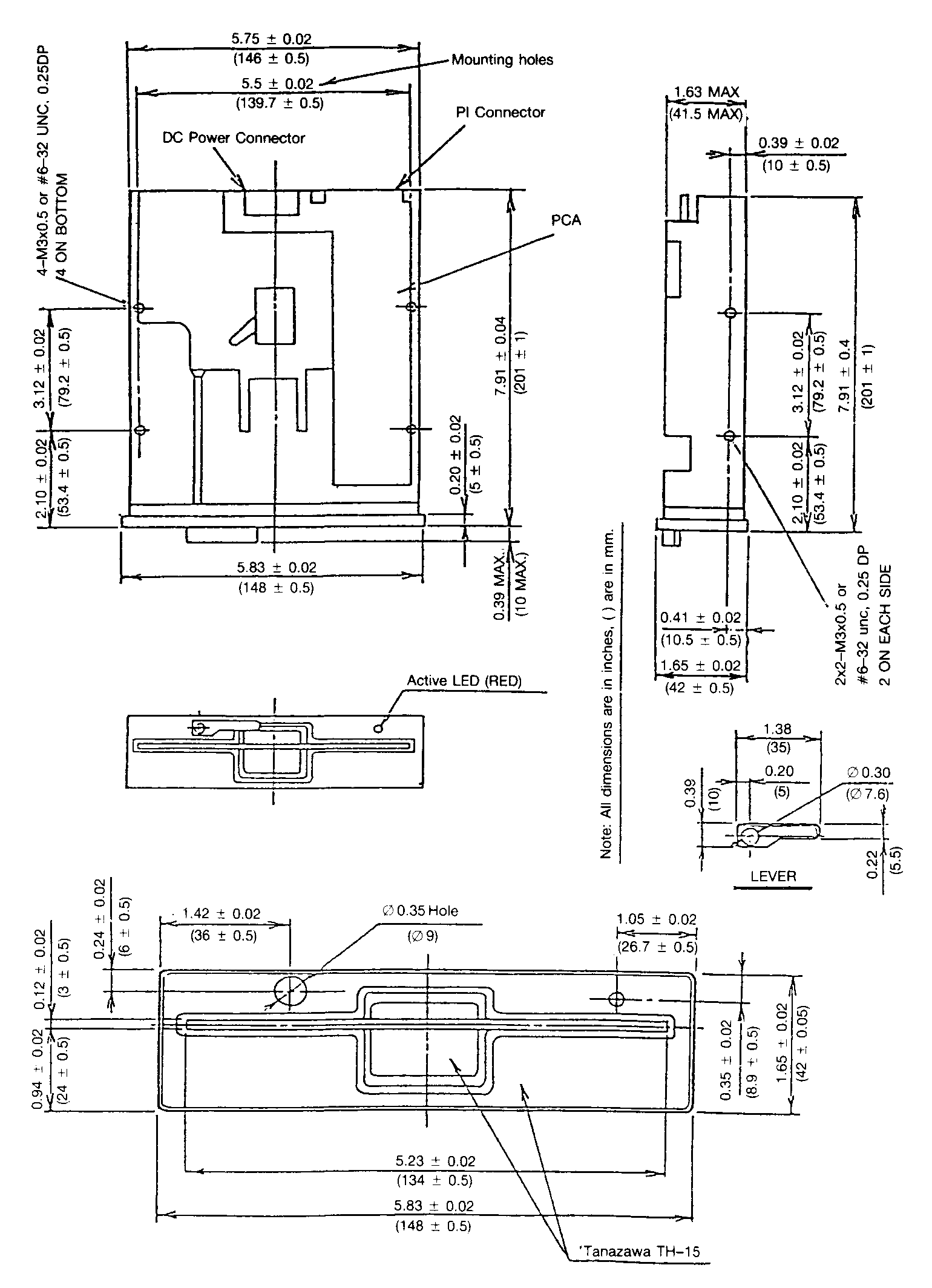
Dimensions
|
Height
41mm
|
Width
146mm
|
Depth
195mm
|
|
Weight
|
1.2Kg
|
|
|
Reliability |
|
|
|
|
|
MTBF
|
10
000 POH or more
|
MTTR
|
30
minutes
|
|
|
Unit
life
|
5
years or 20 000 POH
|
Media
life
|
3.5
million passes/track
|
|
|
Error
rate
|
Soft
error
|
10-9
bit
|
|
|
|
|
Hard
error
|
10-12
bit
|
|
|
|
|
Seek
error
|
10-6
bit
|
|
|
|
DC
power connector
|
|
Pin
number
|
Voltage
|
|
1
|
+12V
DC
|
|
2
|
0V
|
|
3
|
0V
|
|
4
|
+5
VDC
|
|
|
Signal
|
I/O
|
Pin
|
0V
|
|
|
|
*
|
Spare
|
I/P
|
2
|
1
|
*
|
MF504B)
This line switches between high and low density
|
|
|
In
use
|
I/P
|
4
|
3
|
|
|
|
|
Drive
select 3
|
I/P
|
6
|
5
|
|
|
|
|
Index
|
O/P
|
8
|
7
|
**
|
(MF501B)
Standard ready or hold ready available
|
|
|
Drive
select 0
|
I/P
|
10
|
9
|
|
|
|
|
Drive
select 1
|
I/P
|
12
|
11
|
|
|
|
|
Drive
select 2
|
I/P
|
14
|
13
|
**
|
(MF5038
& MF504B)
Standard
ready, hold ready and disk-change available
|
|
|
Motor
on
|
I/P
|
16
|
15
|
|
|
|
|
Direction
select
|
I/P
|
18
|
17
|
|
|
|
|
Step
|
I/P
|
20
|
19
|
|
|
|
|
Write
data
|
I/P
|
22
|
21
|
TTL levels |
|
|
|
Write
gate
|
I/P
|
24
|
23
|
|
|
|
|
Track
00
|
O/P
|
26
|
25
|
Low
level (TRUE) OV to + 0.4V
|
|
|
Write
protect
|
O/P
|
28
|
27
|
High
level (FALSE) + 2.5V to + 5.25V
|
|
|
Read
data
|
O/P
|
30
|
29
|
Input
impedance 150 Ohms
|
|
|
Side
one select
|
I/P
|
32
|
31
|
Receiver:
SN7414N or equivalent
|
|
**
|
Ready
|
O/P
|
34
|
33
|
Driver:
SN7438N or equivalent
|
|
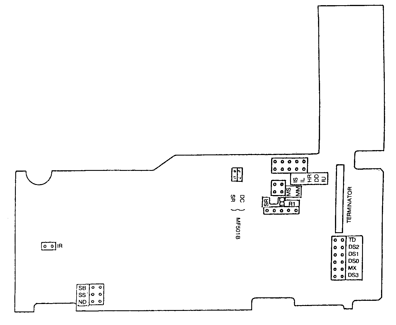
Jumper
name
|
Function
|
|
(DS0)
|
DRIVE
SELECT 0 enables the drive.
|
|
(DS1)
|
DRIVE
SELECT 1 enables the drive. DS2 & DS3 etc.
|
|
(MX)
|
Drive
is selected regardless of DRIVE SELECT lines
|
|
(MM)
MS
|
Motor
controlled by MOTOR ON signal
|
|
MM
(MS)
|
Motor
controlled by DRIVE SELECT signal
|
|
MM
MS
|
Motor
controlled by DRIVE SELECT AND MOTOR ON signal
|
|
(MM)
(MS)
|
Motor
controlled by IN USE signal latched by DRIVE SELECT signal. Option IU must be
jumpered. (MF501B motor controlled by MOTOR ON signal)
|
|
(SR)
DC HR DD
|
Standard
READY sent on pin 34
|
|
(SR)
DC (HR) DD
|
HOLD
READY sent on pin 34 (MF503B, MF504B)
|
|
SR
(DC) HR (DD)
|
DISK
CHANGE (reset by DS) on pin 34 (MF5038, MF504B)
|
|
SR
(DC) HR DD
|
DISK
CHANGE (reset by step) on pin 34
|
|
SR
DC
|
No
ready signal sent
|
|
(RD)
|
Read
data pulses inhibited by READY (MF504B)
|
|
(RI)
|
Index
pulses gated by ready signal
|
|
(SS) SB
|
360
rpm when high density signal sent (MF504B)
|
|
|
300
rpm when low density signal sent (MF504B)
|
|
SS (SB)
|
360
rpm for high and low density (MF504)
|
|
(SS) SB (ND)
|
Low
density 300 rpm set
|
|
|
LED
lighting conditions (MF503B & MF504B)
MF501B
LED is lit by IN USE OR DRIVE SELECT
|
|
(lU)
(IS) (IL)
|
If
IN USE is set, DRIVE SELECT latches LED on
|
|
(IU)
) IS (IL)
|
LED
lit by sum of DRIVE SELECT above conditions
|
|
(IU)
IS IL
|
LED
lit by logical sum of DRIVE SELECT and IN USE.
|
|
(IV)
(IS) IL
|
LED
lit by IN USE signal
|
|
IU
IS IL
|
LED
lit by DRIVE SELECT signal
|
|
IU
(IS) IL
|
LED
will not light
|
|
(IR)
|
May
be used with all the above. Requires that drive is ready before LED will light.
Standard or Hold Ready must be selected if (IR) is used.
|
|
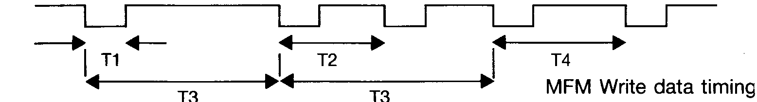
Type
|
T1
|
T2
|
T3
|
T4
|
|
360rpm
HD
|
150
to 1100ns
|
2.0µs
± 10ns
|
4.0µs
± 20ns
|
3.0µs
±15ns
|
|
360rpm
LD
|
150
to 1800ns
|
3.33µs
± 17ns
|
6.7µs
± 33ns
|
5.0µs
±25ns
|
|
300rpm
|
150
to 2100ns
|
4.0µs
± 20ns
|
8.0µs
± 40ns
|
6.0µs
±30ns
|
|
For
MF501B T1= 200 to 2100ns
|

|
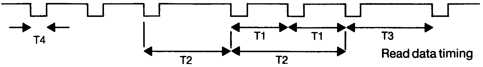
Type
|
T1
|
T2
|
T3
|
T4
|
|
360rpm
HD
|
2.0µs
± 400ns
|
4.0µs
± 800ns
|
3.0µs
± 600ns
|
300ns
± 150ns
|
|
360rpm
LD
|
3.33µs
± 66ns
|
6.67µs
± 1333ns
|
6.0µs
± 1200ns
|
300ns
± 150ns
|
|
300rpm
|
4.0µs
± 800ns
|
8.0µs
± 16000ns
|
6.0µs
± 1000ns
|
300ns
± 150ns
|
|
For
MF503B T4= 1.0µs ± 250ns
|
|
For
MF501B T4= 0.8µs ± 250ns
|
HD
– High density LD – Low density
|
|
|
MF501B
|
MF503B
|
MF504B
|
|
Track
00 sensor
|
TPA
1
|
TPA
1
|
TPA
4
|
|
Read
data output
|
TPA
3
|
TPA
3
|
TPA
3
|
|
Track
00 output
|
TPA
13
|
TPA
13
|
TPA
2
|
|
Index
output
|
TPA
14
|
TPA
14
|
TPA
1
|
|
Differential
head
output
|
TPB
9
TPB
10
|
TPB
9
TPB
10
|
TPB
5
TPB
6
|