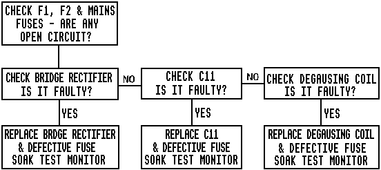
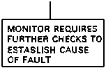
Fig. 1
IMPORTANT: READ THE DESCRIPTION & OPERATION SECTIONS BEFORE ATTEMPTING ANY FAULT ISOLATION OR REPAIR PROCEDURE
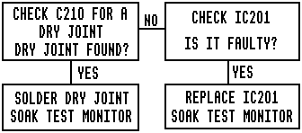
Configured in a boxed flow chart format, it represents repetitive faults encountered by our own Service Technicians. Each fault is accompanied by a series of boxes which will ask you to check a particular part of the equipment. After you have carried out the check a question is asked (refer to Fig. 1).
INTERMITTENT LINE SYNC
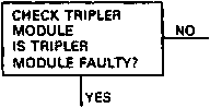
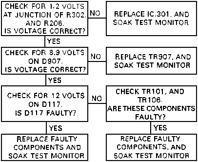
If the answer is NO (as in this case) you must move onto the next box and carry out the next check.
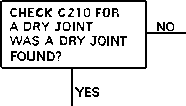
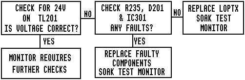
If the answer is YES. the next box will be (refer to Fig. 2).
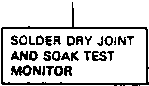
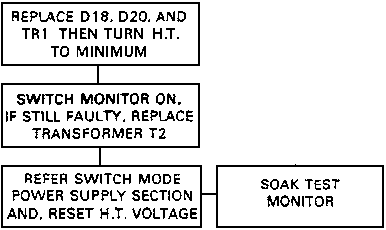
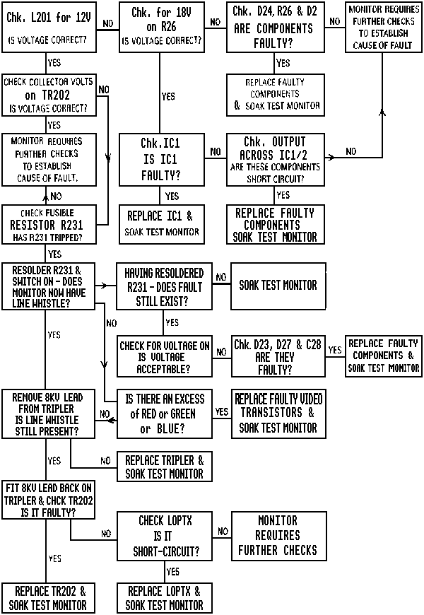
When all the known fault causes have been effected, the chart will be terminated by a box reading: (refer to Fig. 4).
NO PICTURE - LINE OSCILLATING
BURST MODE
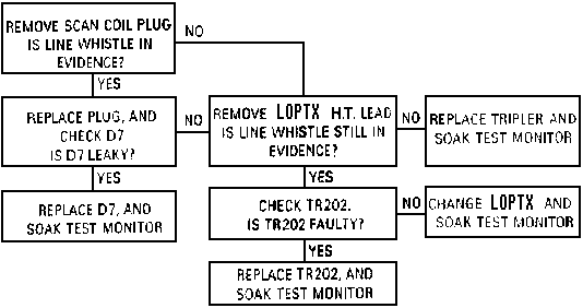
LINE WHISTLE
INTERMITTENT LINE SYNC
FRAME COLLAPSE
MONITOR DEAD - NEON ILLUMINATED
MONITOR HAS NO PICTURE
MONITOR DEAD - NEON NOT ILLUMINATED