This section gives information on how to remove major service items such as:
CRT, Main PCB and Tripler etc..
WARNING: ENSURE MONITOR IS DISCONNECTED FROM MAINS ELECTRICAL SUPPLY
BEFORE EFFECTING THE FOLLOWING OPERATIONS.
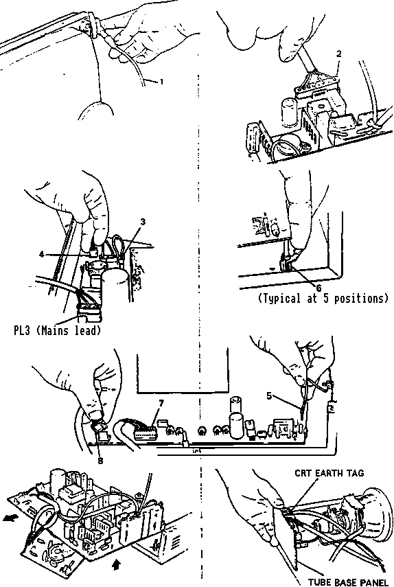
1. Main PCB Removal/Installation (Fig. 1)
- Disconnect EHT lead (1) from CRT. To ensure no charge remains on tripler,
connect to chassis metalwork.
- Discharge CRT, final anode by connecting it to CRT dag.
- Disconnect PL201 (2), PL1 (3) and on cabinet versions PL2 (4) (if fitted)
and mains plug PL3.
- Remove tube base panel and CRT earthing braid tag.
- Remove 'P' band earthing tag (5) from main PCB, located next to
tripler module.
- Release in turn, each of the nylon self-locking PCB support clips (6),
lifting PCB slightly in each case.
- Disconnect PL101 (7), PL102 (8), then disconnect tube base from CRT.
- The main PCB may now be removed by lifting upwards, and withdrawing
from the rear.
- For installation effect the above operations in reverse order.
Main PCB Removal/Installation - Fig. 1
CRT Removal/Installation - Fig. 2
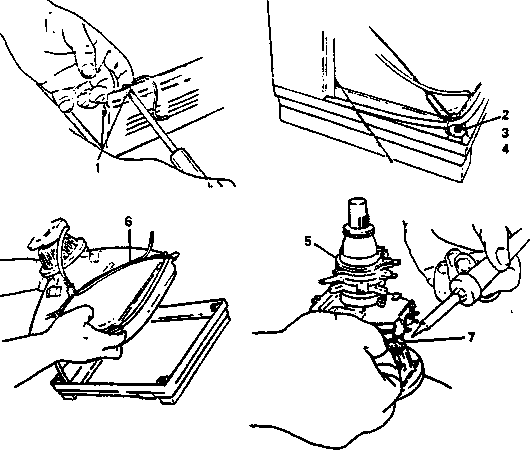
2. CRT Removal/Installation (Fig. 2)
- Effect operations 1.A. thru G., (as above) then position monitor so that
the CRT is face down on two padded support blocks.
- Remove two earthing screws (1), then refer to the Cabinet Parts Listing section and remove the base of the
monitor.
- Remove the four nuts (2) and large washers (3) securing CRT to cabinet
facia (4).
- Carefully withdraw CRT vertically.
- Transfer degauss coil (5) and earthing braid (6) and scan coil lead
assembly (7) to new CRT.
- Install main PCB assembly by effecting operations 1.A. thru G., in
reverse order.
- CRT installation safety checks.
(1) Check for correct fitting of CRT earthing braid (6).
(2) Ensure black lead from CRT earth braid to tube base panel is connected.
(3) Check 'P' band earth pin has been connected to main PCB.
3. Line Output Transistor (TR202) and SMPSU Output Transistor (TR2) -
Removal/Installation (Fig. 3)
- Remove Transistor
(1) Remove two M3 screws (1) securing transistor and heatsink to main PCB.
(2) Unsolder base and emitter connections on PCB, then withdraw transistor
heatsink (4).
(3) Separate transistor from heatsink, retaining insulating bushes (3) and
mica washer (2) for refitment.
- Install Transistor
(1) Coat underside of transistor with thermally conductive heatsink
compound.
(2) Effect operations 3.A.(1) thru (3), in reverse order.
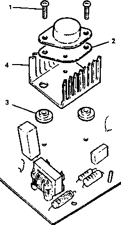
Fig.3: Line Output Transistor
and SMPSU Output Transistor Removal/Installation | |
4. Tripler - Removal/Installation (Fig. 4)
- Tripler Removal
(1) Remove EHT lead from CRT and discharge CRT final anode to the earth braid.
(2) Unsolder the following: Lead from line output transformer overwind (1);
focus lead (2) to tube base panel at the tripler end.
(3) Unsolder from main PCB: Earth return (3) from focus control; clamp diode
earth return (4)
(4) Loosen, but do not remove tripler securing screws (5), then withdraw
tripler module (6) from main PCB.
- Tripler Module - Installation
(1) Position tripler module (6) on main PCB assembly and secure with
screws (5).
(2) Solder on main PCB: Earth return (3) from focus control; clamp diode
earth return (4).
(3) Solder: Lead from line output transformer overwind (1); focus lead
(2) to tube base panel at the tripler end. Replace insulation sleeve on
connection (2).
NOTE: Ensure all soldered connections are smooth and connecting wires
kept as short as possible, to guarantee adequate voltage clearances.
(4) Connect EHT lead to CRT final anode.
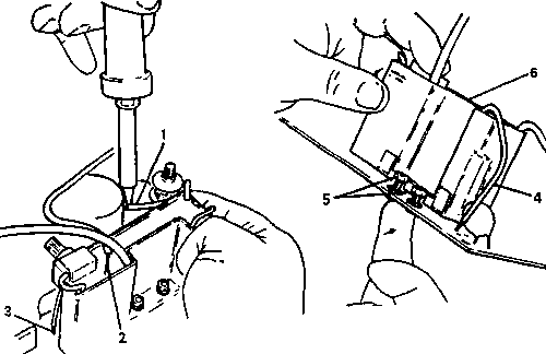
NOTE: Replace the insulation sleeve on connection (2)
Tripler Removal/Installation Fig. 4
TYRAP POSITIONS ON CABINET BACK COMPONENTS
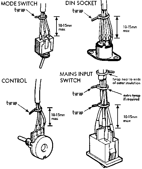
Note: All tyraps to be fully tight
MODIFICATION FOR IBM/APPLE INTERFACES
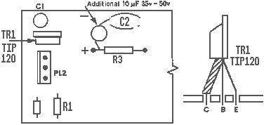
(1) Remove TR1 (BC337) and replace with TIP 120 as shown.
(2) Remove R1 (6K8) and replace with 8K2 ¼W 5%.
(3) Place a 10microfarad 35V electrolytic as follows:
(i) negative side, to top of existing C4 position
(ii) positive side, mechanically wrapped around and soldered to left side of
R3.