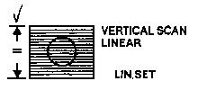
(VERTICAL LINEARITY)
Preset controls are initially set up at the factory and normally do not require adjustment unless a change is required in the input configuration - for example, typically to install a different graphics adaptor card in the associated host system. Details of the preset controls with their use and adjustment is described following:
TO PROTECT AGAINST ELECTRICAL SHOCK HAZARD AND TO PROTECT THE MONITOR AGAINST SHORT CIRCUIT AND DAMAGE - USE ONLY AN INSULATED NON-METALLIC TRIMMING TOOL TO MAKE ADJUSTMENTS TO THE PRESET CONTROLS.
Care should be taken when adjusting presets. Adjust only one at a time and note carefully the effects of the adjustment before proceeding on to other adjustments. In some cases, it may be advisable to take note of the original setting position of the preset BEFORE adjustment in case the need arises to return to the original setting.
INTERCONNECTION COMPATIBILITY
On installation and prior to preset adjustments, ensure that video and sync connections from the host system are compatible with:
PRESET CONTROL SETTINGS
However, normally this should not be necessary, as these presets are set accurately at the factory during manufacture.
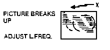
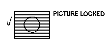
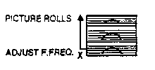
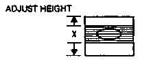
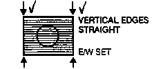
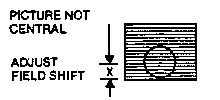
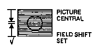
NOTE: A circle is employed in the screen displays illustrated following, only to demonstrate more clearly the geometric effects of wrong settings.
The physical locations of most of the preset controls referred to in the descriptions following are shown in the PCB and Tube Base layout diagrams. The positions of these presets are indicated on the individual PCB's by appropriate ident markings.
TABLE OF PRESET ADJUSTMENTS
| PRESET | WRONG X | RIGHT / |
|---|---|---|
| LINE FREQUENCY | |
|
| FIELD FREQUENCY | |
|
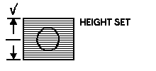
| HEIGHT | |
|
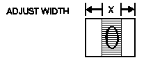
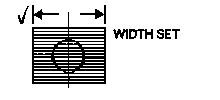
| WIDTH | |
|
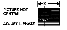
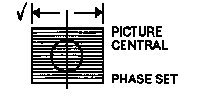
| LINE PHASE* | |
|
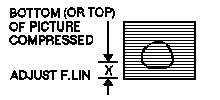
| FIELD LINEARITY* (VERTICAL LINEARITY) | |
|
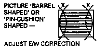
| EAST/WEST* CORRECTION | |
|
| FIELD SHIFT | | |
All pre-set adjustments are included in this section. You are given the prefix for example: Field Linearity VR312. If you are not sure of the location of any pre-set (or component) then you should refer to the section containing PCB or CRT base panel layouts. Once you have located the pre-set, you are then told what effect the adjustment will have on the display.
NOTE: Certain preset adjustments can be from above or below main panel. Adjustments are best made on a static display, preferably a MICROVITEC test card, details of test equipment are available on application.
1. Set HT VR4
WARNING: THIS IS A CRITICAL SAFETY ADJUSTMENT, FAILURE TO COMPLY WITH THE ABOVE WILL INVALIDATE THE WARRANTY.
NOTE: VR220 when adjusted will shift the picture, right or left.
Using a non-metalic trimming tool adjust L202, to effect picture width adjustment. 6. Height VR306
NOTE: Best results are obtained by using a cross hatch type grid or MICROVITEC test generator.
Adjustment of VR328 will achieve straight verticals on left and right hand sides of picture.
(1) Set customer contrast (VR111), brightness (VR134) and A1 (VR932) fully anti-clockwise
(2) Disconnect R,G,B, sync inputs
(1) Adjust VR906 for red cathode (black level) volts
(2) Adjust VR914 for green cathode (black level) volts
(3) Adjust VR921 for blue cathode (black level) volts
(4) The above voltages are:
(a) 150V - 14" monitor (TTL or Linear)
(b) 155V - 20" monitor (TTL or Linear)
(c) 140V - 12"/14" high res monitor (TTL or Linear)
(1) Adjust VR932 until a raster is just visible.
(2) Raster colour may be neutral. However, it is very likely shaded
towards red, green, blue or a combination of any two colours.
(3) Establish raster colour shading as follows:
(a) Red and Green - Yellow
(b) Red and Blue - Magenta
(c) Blue and Green - Cyan
(4) Reduce black level of remaining one or two guns using VR906, VR914,
VR921 or combination until a neutral raster is achieved.
(5) Re-adjust VR932 to just extinguish raster
(6) Input - R,G,B and sync signals, then adjust VR111 clockwise
(7) If correct white balance has not been achieved, repeat operations C. (1)
thru (6).
(1) Disable beam current limit circuit, by removing TL901 in series with CRT
heaters on tube base panel.
(2) Provide a test pattern with peak white and black level information on
red, green and blue.
(3) Ensure VR111 is fully clockwise to provide maximum drive voltages to
video output stages.
(1) Adjust VR903, for red peak to peak drive volts at R926.
(2) Adjust VR910, for green peak to peak volts at R925.
(3) Adjust VR916, for blue peak to peak volts at R924.
(4) Above voltages are:
(a) 70V p-p on 14" monitor - TTL mode
(b) 70V p-p on 20" monitor - TTL mode
(c) 60V p-p on 14"/20" monitor - medium and high resolution