 or
coloured GREEN, or GREEN and YELLOW.
or
coloured GREEN, or GREEN and YELLOW.
GP0019AA2
1. MODELS - 1431/1432 | |
| SYSTEM | 1: 625 lines, 50 fields interlaced
or 312/313 lines, 50 fields non interlaced 2: 525 lines, 60 fields interlaced or 262, 263 lines. 60 fields non-interlaced other non-standard systems may be suitable -consult MICROVITEC PLC. |
| SUPPLY | Nominal 180 - 265V, 40 to 64Hz |
| TIMEBASE (LINE) | Pull-in range 15 to 16KHz |
| FRAME FREQUENCY | 50Hz - Pull-in range 45 to 65Hz |
| POSITIONAL ERROR | ±3% |
| CONVERGENCE ERROR | 0.6mm screen center 1.6mm screen edge |
| EHT | 24KV approximately |
| EHT REGULATION | ±1KV |
| LINE FREQUENCY | 15.625KHz |
| DEGAUSING | Automatic at switch ON |
| BANDWIDTH | 18MHz |
| RESOLUTION | 452(H)x585(V) elements |
| DOT PITCH | 0.64mm |
| CRT | Rectangular 335.4mm (screen diagonal)
90 deg deflection. Precision in-line gun vertical stripe screen, high voltage focus |
| INPUTS MODEL 1431 | TTL compatible; 1500 ohm R, G, B inputs link selectable, positive or negative video |
| INPUTS MODEL 1432 | Linear; 0 to 4V 1500 ohm R, G, B
inputs. Positive video, composite or separate line and field synchronisation - each link selectable positive or negative |
| INPUT CONNECTOR | 10 pin in-line 'SYSTEM 25' Pressac |
| OPERATING TEMP | 0 to 55 deg C (max) open chassis -10 deg C to +40 deg C (max) |
| POWER CONSUMPTION | 65W approx. |
2. MODELS 1441 AND 1442 14" HIGH RESOLUTIONNOTE: As models 1431 and 1432, with the following exceptions: | |
| CONVERGENCE ERROR (MAX) | 0.3mm screen center 0.8mm screen edge |
| EHT | Approx. 24KV |
| BANDWIDTH | 18MHz |
| RESOLUTION | 895(H)x585(V) elements, rectangular 333mm
(screen diagonal)
Automatic degausing at switch on. High focus voltage in-line gun. 90 deg. diagonal deflection, 0.31mm dot pitch black matrix screen with pigmented phosphors. |
| DOT PITCH | 0.31mm |
| POSITIONAL ERROR | ±2% |
| CONVERGENCE ERROR | 0.8mm screen edge |
3. MODEL 1451NOTE: As models 1431 and 1432, with the following exceptions: | |
| RESOLUTION | 652(H)x585(V) |
| DOT PITCH | 0.43mm |
| CONVERGENCE ERROR | 1.2mm screen edge |
4. MODEL 2030NOTE: As models 1431 and 1432, with the following exceptions: | |
| CONVERGENCE ERROR (MAX) | 0.4mm screen center 1.8mm screen edge |
| RESOLUTION | 505(H)x585(V) elements, 80 characters on 6 dot, wide matrix |
| DOT PITCH | 0.8mm |
| CRT | Rectangular 480mm (screen diagonal) 90 deg deflection precision in-line gun vertical stripe screen high voltage focus |
| POWER CONSUMPTION | 80W approx. |
5. MODEL 2040NOTE: As models 1431 and 1432, with the following exceptions: | |
| RESOLUTION | 940(H)x705(V) |
| DOT PITCH | 0.47mm |
| POSITIONAL ERROR | ±4% |
| POWER CONSUMPTION | 80W approx. |
| CONVERGENCE ERROR | 1.0mm screen edge |
ELECTRICAL SUPPLY
Warning
THIS APPARATUS MUST BE EARTHED.
Important
The wires in the mains lead are coloured in accordance with the following code:
GREEN AND YELLOW : EARTH
BLUE : NEUTRAL
BROWN : LIVE
As the colours of the wires in the mains lead may not correspond with the coloured markings identifying the terminals in your plug, proceed as follows:
or
coloured GREEN, or GREEN and YELLOW.
X-rays constitute a health hazard on prolonged exposure at close range unless adequate shielding is provided.
Precautions must be exercised during servicing of display equipment to ensure that the anode voltage and other tube voltages are adjusted to the recommended values.
Replace with a tube of the same type number or recommended replacement to assure continued safety.
Implosion Protection
This tube employs integral implosion protection and must be replaced with a tube of the same type or a recommended replacement to assure continued safety.
Shock Hazard
The high voltage at which the tube is operated may be very dangerous. Extreme care should be taken in the servicing or adjustment of any high voltage circuit. Caution must be exercised during the replacement or servicing of the tube since a residual electrical charge may be contained on the high voltage capacitor formed by the external and internal conductive coating of the tube funnel. To remove any undesirable residual high voltage charges from the tube, "bleed off" the charge by shorting the anode contact button, located in the funnel of the tube, to the external conductive coating before handling the tube.
Tube Handling
Wear heavy protective clothing, including gloves and safety goggles with side shields. Handle the tube with extreme care. Do not strike, scratch or subject the tube to more than moderate pressure. Particular care should be taken to prevent damage to the seal area.
OPERATING SAFETY
We recommend - after effecting any Service and/or replacement of any part of the monitor, or after any repair work - that the SAFETY CHECKS listed following are carried out.
Ensure on re-assembly that ALL earth connections are replaced SECURELY; in particular safety earths and the 'P' band and dag earth 'CRT' earth connections.
Important!
Failure to observe the points noted could affect your own safety, the product's safety and ultimately, that of the user.
Earth Continuity Check
Check between 'Dag' earth on the CRT and mains plug earth pin, (safety earth connection). The reading should be less than 470Kohm (with tube discharged).
2) PCB 'Earth' pin on main chassis
and ALL exposed
metalwork.
Note
Tests b and c should have a resistance of less than 0.5 ohm.
for leakage breakdown.On Test
1) No breakdown should occur.
2) Earth leakage should be less than 6mA at 1.5KV.
CAUTION
A MONITOR FAILING ANY OF THE ABOVE CHECKS MUST BE RESTORED TO SAFE WORKING CONDITION BEFORE BEING RETURNED TO THE USER.
UNDER NO CIRCUMSTANCES SHOULD ANY FORM OF REPAIR OR MAINTENANCE BE ATTEMPTED BY ANY PERSON OTHER THAN A QUALIFIED ENGINEER.
Switched Mode Power Supply
Although the outputs from the power supply are isolated from the incoming mains supply, the bridge rectifier and the control and regulation circuit ARE NOT isolated. Therefore, when servicing the power supply section of the chassis assembly, the SMPSU should be supplied by a MAINS ISOLATION TRANSFORMER OF AT LEAST 300VA RATING.
HANDLING PRECAUTIONS
HT Electrical Charges
The power supply section remains charged with respect to chassis for 30-60 seconds after switching off. Care should be taken when handling the chassis to avoid touching this area during this time.
EHT Charges - Horizontal (Line) Output Stage/CRT
Before handling or attempting adjustment or replacement on the horizontal (line) output stage or on CRT areas - always discharge the final anode of the CRT - by using a suitable EHT probe only. Do this by connecting first to CRT dag earth coating/earth braid assembly, and then to CRT final anode/anode button 'poppy' connector.
Very considerable electrical charges can be stored in these areas - even for lengthy periods of time after 'switch off'.
In the interests of your personal safety observe the precautions listed.
Components marked  on the parts list and circuit
diagram are safety approved types and they should be replaced only with
components supplied or approved by our Service Department. It is also
recommended that the components not marked with the safety symbol should
be replaced by parts of the type originally fitted, and this applies
particularly to those resistors which are stood off the printed circuit
boards.
on the parts list and circuit
diagram are safety approved types and they should be replaced only with
components supplied or approved by our Service Department. It is also
recommended that the components not marked with the safety symbol should
be replaced by parts of the type originally fitted, and this applies
particularly to those resistors which are stood off the printed circuit
boards.
HANDLING PRECAUTIONS - STATIC ELECTRICAL CHARGES
Depending on equipment type and model, the equipment may contain devices
which may be damaged by static electrical charges during handling.
Generally, these devices are indicated by a  symbol.
When replacing or handling these devices or PCBs containing such devices, care should be taken. Soldering irons should be earthed and personnel should use wrist straps earthed via a 1Mohm resistor. If the latter is not practicable they should discharge themselves of any static electricity by touching an earthed point
Static sensitive devices should be packed in suitable conductive containers.
Electrostatic discharge does not necessarily 'kill' a component completely - more likely it will 'wound' it.
Many static wounded devices will pass normal test both on site and in Service Workshops. In this respect PCBs containing such 'wounded' devices are a major cause of 'no fault found' problems.
It pays, therefore, to cultivate static safe ways when dealing with such static sensitive equipment
NOTE: Monitors are normally despatched wired in composite negative (going) syncs mode, with TL102 not fitted, and TL106 selected to position 1.
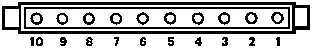
KEY
 1 = +12V
 2 = No connection
 3 = Sync 3: field sync
 4 = Red video
 5 = Sync 2: field sync
 6 = Green video
 7 = Sync 1: composite or line sync
 8 = Blue video
 9 = Normal/inverse T.T.L. video
10 = Ground
4. Synchronisation Options
| SYNC OPTIONS | INPUTS (PL101) | LINK POSITION |
|---|---|---|
| MIXED -ve going +ve going | pin 7 pin 7 | TL102 not fitted TL106 in position 1 TL102 fitted TL106 in position 1 |
| SEPARATE -ve line -ve field +ve line +ve field -ve line +ve field | pin 7 pin 5 pin 7 pin 3 pin 7 pin 3 | TL102 not fitted TL106 in position 1 TL102 fitted TL106 in position 2 TL102 not fitted TL106 in position 1 |