8-Bit Software
The BBC and Master Computer Public
Domain Library
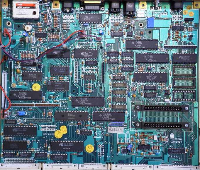
Inside The Master 128
 [Back to Insides]
IC1
7406 TTL 14/0-3
IC2
7438 TTL 14/0-3
IC3
WD1770 FDC 5.25''
IC4
74LS174 TTL 16/0.3
IC5
71lLS244 LL 20/0-3
IC6
6522 VIA NM0S 1MHZ
IC7
74LS373 LL 20/0-3
IC8
6522 VIA NM0S 1MHZ
IC9
LM324 QUAD 0P AMP
IC10
71lLs259 LL 16/0.3 option 74ALS259 LL 16/0.3
IC11
6818 RTC CM0S
IC12
761189 S0UND GEN
IC13
IC LM386 AUDIO AMP
IC14
65C12 CPU CM0S 2MHZ
IC15
MSI I/0 CTRL (CF30050)
IC16
MSI KEYBD ENC (CF3001l7)
IC17
4464 DRAM 120nS 64Kx4
IC18
4464 DRAM 120nS 64Kx4
IC19
74LS14 TTL 14/0.3
IC20
MSI MEM SW (CF30058)
IC21
MSI P.B.C. (CF300119)
IC22
68115 CRTC NM0S 1MHZ
IC23
4464 DRAM 120nS 64Kx4
IC24
EROS 1MB ROM
IC25
74LS86 TTL 14/0.3 option 74ALS86 TTL 14/0.3
IC26
4464 DRAM 120nS 64Kx4
IC27
SKT IC 28/0.6 NORM
IC28
74F74 LL 14/0.3
IC29
74HCT253 CM0S 16/0.3
IC30
74LS257 LL 16/0.3 option 711ALS257 LL 16/0.3
IC31
MSI CRTC MUX (CF3001l8)
IC32
SAA5050 CHTR GEN
IC33
74HCT253 CM0S 16/0.3
IC34
74S00 TTL 14/0-3
IC35
Empty
IC36
74F00 TTL 14/0.3
IC37
SKT IC 28/0.6 NORM
IC38
74LS00 TTL 14/0.3 option 74ALS00 TTL 14/0.3
IC39
74LS02 TTL 14/0.3
IC40
CF30060
IC41
SKT IC 28/0.6 N0RM
IC42
VIDEO PROCESSOR
IC43
74S04 TTL 14/0.3
IC45
6850 ACIA NM0S 1MHZ
IC46
LM324 QUAD 0P AMP
IC48
SERIAL PROCESSOR
IC49
7002 ADC 12 BIT
IC50
3691 RS422/423 DRVR
IC51
9637A RS422/423 RCVR
Keyboard
General description:- 93 keys are provided. 92 of these are in a modified
8 x 13 matrix as shown in figure 5. A keyboard encoder, IC16 is used to
scan the keyboard. During idle (free run) mode, pressing any key will cause
an IRQ to be generated via the system 6522. A connection is provided from
IC16 to a 6522 'CA' type connection. Hence the interrupts thus generated
are controlled by the 6522 control register. Depression of either of the
shift keys, or the control key does not cause an interrupt to occur.
Keys are arranged as a QWERTY style keyboard with extra keys for a numeric
keypad. Ten additional 'function keys' together with cursor control buttons,
etc., are provided.
The "BREAK" key will reset the CPU and abort any access to the clock/RAM
chip. To prevent accidental operation, a mechanical lock is provided. This
is a plastic cam which is rotated through 90 degrees to stop the keytop
from being depressed.
Keyboard Operation:- During free run mode, the keyboard column lines
are continually scanned by incrementing a counter, decoding its outputs
and pulling low a column line. Any key depressed will cause the interrupt
to be generated. A signal, KeyBoard ENable is generated to stop free running
mode. The counter contents are now loaded by CPU operation to determine
on which row the key was pressed. The rows are then individually selected
to determine which key was pressed.
LK12
3w WAFR 0.1 ST PCB
Plug, made B (East): CSYNC/Cartridge Machine Detect.
Two position link.
Position A - This connection to the computer CSYNC line is provided
for
GENLOCK purposes.
Position B - Certain hardware cartridges may need to detect whether
they are plugged into a Master Series computer or an Acorn Electron. Master
computers are shipped with this link in the B position, causing a logic
LOW to appear on pin A10 of the cartridges. The Electron has no connection
to this pin.
9 Issue 1
LK18
3w WAFR 0.1 ST PCB
plug, made West: Paged ROM/RAM Select.
Two position link.
When fitted in the West position, this link causes 16Kbyte of RAM to
appear in each of the "sideways" memory "slots" 6 and 7.
When fitted in the East position, a 32Kbyte ROM occupying slots 6 and
7 may be plugged into socket labelled IC41.
10 Issue 1
LK19
3w WAFR 0.1 ST PCB
plug, made West: Paged ROM/RAM Select.
Two position link.
When fitted in the West position, this link causes 16Kbyte of RAM to
appear in each of the "sideways" memory "slots" 4 and 5.
When fitted in the East position, a 32Kbyte ROM occupying slots 4 and
5 may be plugged into socket labelled IC37.
MD1
MODUL UHF PAL WB E36
PAL/NTSC encoded, UHF carrier On channel 36 with 1.5mV into 75 ohm.
For use with NTSC, the modulator. has to be changed from UM1233/E36
to a VHF equivalent. Provision is made for selection of either one of two
channels with V.H.F. A Molex type link has to be inserted for this.
PSU
The power supply unit is connected to the main circuit board by seven push-on
connectors which must be unplugged. Three screws on the underside of the
case are undone allowing the unit to be removed. On reassembly, ensure
that the same type of screw is used (M3x6mm).
IDC Connectors
All IDC connector pins are numbered in this way:
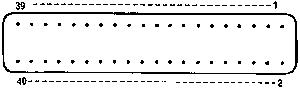
PL1
34w HDR IDC RA 4 WALL 2
Disc Drive
1 0V 2 (notS/SEL 8'' )
3 0V 4 (notINX 8'')
5 0V 6 NC
7 0V 8 notINX 5 1/4"
9 0V 10 notS0
11 0V 12 notS1
13 0V 14 NC
15 0V 16 notMOTOR
17 0V 18 notDIR
19 0V 20 notSTEP
21 0V 22 notW/DATA
23 0V 24 notWR/EN
25 0V 26 notTK0
27 0V 28 notWR PCT
29 0V 30 notR/DATA
31 0V 32 notS/SEL 5 1/4"
33 0V 34 (notRDY 8")
PL3
26w HDC IDC RA 4 WALL
Printer
1 STB 2 0V
3 PA0 4 0V
5 PA1 6 0V
7 PA2 8 0V
9 PA3 10 0V
11 PA4 12 0V
13 PA5 14 0V
15 PA6 16 0V
17 PA7 18 0V
19 ACK 20 0V
21 NC 22 0V
23 NC 24 0V
25 NC 26 NC
PL4
20W HDC IDC RA 4 WALL
User Port
1 +5V 2 CB1
3 +5V 4 CB2
5 0V 6 PB0
7 0V 8 PB1
9 0V 10 PB2
11 0V 12 PB3
13 0V 14 PB4
15 0V 16 PB5
17 0V 18 PB6
19 0V 20 PB7
PL5
34w HDR IDC RA 4 WALL 2
1MHz Bus
1 0V 2 R/notW
3 0V 4 1E
5 0V 6 notNMI
7 0V 8 notIRQ
9 0V 10 notPGFC
11 0V 12 notPGFD
13 0V 14 notRS
15 0V 16 audio in/out (see LKl)
17 0V 18 D0
19 D1 20 D2
21 D3 22 D4
23 D5 24 D6
25 D7 26 0V
27 A0 28 A1
29 A2 30 A3
31 A4 32 A5
33 A6 34 A7
PL6
110w HDR IDC RA 4 WALL
Tube
1 0V 2 R/notW
3 0V 4 2E 5 0v
6 notIRQ 7 0V
8 notTUBE 9 0V
10 notRS 11 0V
12 D0 13 0V
14 D1 15 0V
16 D2 17 0V
18 D3 19 0V
20 D4 21 0V
22 D5 23 0V
24 D6 25 0V
26 D7 27 0V
28 A0 29 0V
30 A1 31 +5V
32 A2 33 +5V
34 A3 35 +5V
36 A4 37 +5V
38 NC 39 +5V
40 NC
PL8
3w WAFR 0.1 ST PCB
PL9
2W WAFR .1 RA PCB
PL10
5W WAFR 0.1'' RA 11PIN
PL17
TAB 6.3mm ST PCB
PL18
TAB 6.3mm ST PCB
PL19
TAB 6.3mm ST PCB
PL20
TAB 6.3mm ST PCB
PL21
TAB 6.3mm ST PCB
PL22
TAB 6.3mm ST PCB
PL23
TAB 6.3mm ST PCB
RL1
RLY 1P C0 5V 50R PCB
Cassette Relay
SK1
12W SKT HSNG 0.1 PCB
Expansion Board Slot
SK2
12W SKT HSNG 0.1 PCB
Expansion Board Slot
SK3
12W SKT HSNG 0.1 PCB
Cartridge Slot
SK4
12W SKT HSNG 0.1 PCB
Cartridge Slot
SK5
19w SKT HSNG 0.1 PCB
Econet Board Slot
SK6
5W SKT HSNG 0.1 PCB
Econet Board Slot
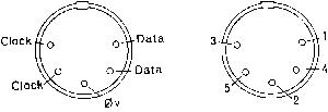
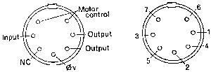
SK7
5W SKT DIN RA PCB
Econet Din Plug
SK8
BNC SKT 75R PNL
BNC Video Out
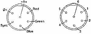
SK9
6w SKT DIN RA PCB
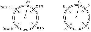
RGB
SK10
5W SKT DIN RA D0M
RS423
SK11
7w SKT DIN RA PCB
Cassette
SK12
15W SKT D RA E2.84
Analogue in
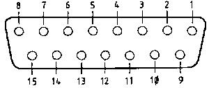
1 +5V
2 0V
3 0V
4 CH3
5 analogue ground
6 0V
7 CH1
8 analogue ground
9 light pen strobe (notLPSTB)
10 digital switch input (I1)
11 voltage reference (VREF)
12 CH2
13 digital switch input (IO)
14 voltage reference (VREF)
15 CH0
SK13
PHONO SKT RA PCB
Audio Out
PSU
[Back to Insides]